Tag Archives: mechanical seal

Online simulation of mechanical seals is now possible

As explained in the previous posts (link), the behavior of mechanical seals is governed by several physical phenomena in interaction: lubrication, asperity contact, heat transfer, deformation. It makes the analytical calculation of mechanical seals complicated.

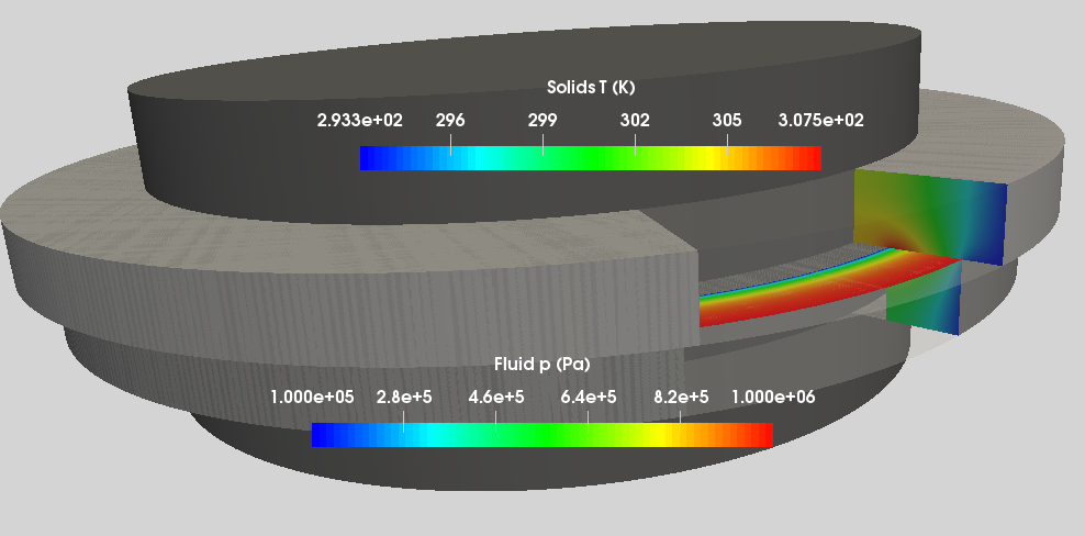
The software SimMS (Simulation of Mechanical Seal) that I developed at Institut Pprime is now available online (SimMS Online) thanks to Uniwaresity. It is a useful tool to compute the behavior of mechanical seal.

> Try it

Example of simulation with SimMS (source Uniwaresity)

Analytical modelling of mechanical face seals: post #4

Analytical model for full film lubrication

In this post, a first model for full film lubrication is proposed. It will allow to determine the seal faces temperature, the thickness of the film between the faces, the friction torque, etc.

If the distance between the faces is assumed to be equal to the mean film thickness, the dissipated power by viscous friction is:

P=\mu \omega^2 S_f \frac{\left( r_o+r_i\right)^2}{4 h_m}

This power is transferred to the seal rings by conduction. According to post# 1, we have:

E_t \Delta T=\mu \omega^2 S_f \frac{\left( r_o+r_i\right)^2}{4 h_m}

According to post# 3, the film thickness is given by:

h_m=\frac{\beta \Delta R}{4 \left(B_t-0.5 \right)}

The coning angle \beta is due to the faces deformations as explained in post #2:

\beta=N \Delta T+\beta_e

Finally, the fluid viscosity  \mu is a function of the local temperature. By using an exponential law, we have:

\mu \left(\Delta T\right)=\mu_0 \exp \left(-\alpha \Delta T\right)

where \mu_o is the viscosity at the reference temperature and \alpha the thermoviscosity coefficient.

A non linear equation of the seal faces temperature is obtained:

E_t \Delta T=\mu_0 \exp{\left( -\alpha \Delta T\right)} \omega^2 S_f \frac{ \left( r_o+r_i \right)^2 \left( B_t-0.5 \right) }{ \left( N \Delta T+\beta_e \right) \Delta R }

It is convenient to use a dimensionless form of this equation. For that a temperature scale based on the thermoviscosity coefficient is used:

\bar{T}=\Delta T \alpha

Then the previous non linear equation temperature becomes:

\bar{T}=\exp{\left(-\bar{T}\right)}\frac{Se}{\bar{T} + Co}

In this equation Se is the sealing number and is a kind of thermal loading number of the seal face:

Se=\mu_o \pi \omega^2\frac{\left( r_o+r_i \right)^3\left( B_t-0.5 \right) }{E_t N }

The second dimensionless number, Co, is the coning number. It represents an initial coning of the faces due to mechanical loading (fluid pressure) or wear of the faces:

Co=\frac{\beta_e \alpha}{N}

According to governing equation, the seal faces temperature rises with the sealing number, Se. However, the magnitude of this temperature is reduced by the decrease in viscosity with temperature (exponential term) and the increase in film thickness with temperature (denominator). A positive initial coning number, Co , will increase the film thickness and thus reduce temperature whereas a negative value will produce the invert.

The governing equation can be easily solved by using Excel for example. When the temperature of the faces is known, it is then possible to compute the film thickness, the leakage flow, the friction torque, etc. The next figure presents the dimensionless temperature rise as a function of the sealing number for different values of the coning number.

In the case of negative coning number, the temperature can not be lower than -Co to avoid negative coning and film thickness. This situation is not realistic and will lead to faces contact. To analyze

this effect, the minimum film thickness can be expressed in a dimensionless form:

\bar{h}_{min}=Co+\bar{T}


The film film thickness is presented as a function of the sealing number; Se, for different values of the coning number Co in the next figure. As expected the film thickness is an increasing function of Se. For positive coning number, the minimum film thickness can not decrease below a threshold avoiding faces contact. For negative or null values of Co, the film thickness can reach zero at low sealing number values. In this case face contact will be experienced. According to my experience, the dimensionless film thickness corresponding to the appearance of contact (three times the r.m.s roughness height), is approximately equal to 0.5. Above this value, the present model is correct. Below this threshold mixed lubrication is expected to occur. This boundary between full film and mixed lubrication regimes has been added on the temperature map (dashed curve):

0.5=Co+\bar{T}

It is now necessary to consider contact between the surfaces of the seal.

References

Brunetière, N. & Apostolescu, A. A Simple Approach to the ThermoElastoHydroDynamic Behavior of Mechanical Face Seals Tribology Transactions, 2009, 52, 243-255


Analytical modelling of mechanical face seals: post #3

Seal faces lubrication

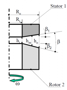
In this post, we will determine the fluid force developed between the seal faces. For that the following assumptions are used (Brunetière and Apostolescu, 2008):

  1. The problem is axisymetric,
  2. The faces are separated by an isoviscous full fluid film
  3. The seal faces are perfectly coned
  4. The seal is narrow so that its curvature can be neglected.

The configuration of the problem is described on the next figure.

The pressure distribution p is governed by the following Reynolds equation:

\frac{d}{dr}\left( h^3 \frac{dp}{dr}\right) =0

Because of the coning \beta, the radius r and the film thickness h are linearly linked:

h=h_i+\beta \left(r-r_i \right)

The Reynolds equation is now:

\frac{d}{dh}\left( h^3 \frac{dp}{dh}\right)=0

An analytical expression of the pressure is obtained. If the inner pressure is zero, it is:

p\left( h \right)=p_o\left( \frac{h_o^2}{h^2}\frac{h^2-h_i^2}{h_o^2-h_i^2}\right)

By integrating the pressure over the seal surface S_f, the fluid opening force F_o is obtained as a function of the film thickness and the outer pressure p_o:

F_o=p_o\frac{h_o}{h_o+h_i}S_f= p_o\frac{2h_m+\beta \Delta R}{4h_m}S_f

This force must be balanced by the closing force F_c due to the sealed fluid pressure and elastic elements. These forces are described on the next figure.

The closing force can be expressed in this way:

F_c=p_o\left(B+\frac{F_s}{p_o S_f} \right)S_f=p_oB_tS_f


B_t is a global balance ratio including the effect of the fluid and the spring force F_s. If the fluid pressure is high enough, the total balance ratio is equal to seal balance ratio B=\frac{r_o^2-r_h^2}{r_o^2-r_i^2}

The force balance leads to an equation giving the mean film thickness $h_m$ as a function of the total balance ratio and the coning angle:

h_m=\frac{\beta \Delta R}{4 \left(B_t-0.5 \right)}

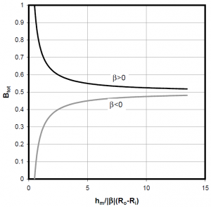
As illustrated on the next figure, a positive coning angle is necessary to obtain a stable full fluid film as demonstrated by Green and Etsion (1985). Moreover, the balance ratio must be higher than 0.5 to avoid an opening of the seal and lower than 1 to prevent from faces contact.


References

Brunetière, N. & Apostolescu, A. A Simple Approach to the ThermoElastoHydroDynamic Behavior of Mechanical Face Seals Tribology Transactions, 2009, 52, 243-255

Green, I. & Etsion, I. Threshold and Steady-State Response of Noncontacting Coned-Face Seals ASLE Transactions, 1985, 28, 449-460

Analytical modelling of mechanical face seals: post #2

Deformation of the seal faces

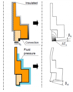
The second step of the model concerns deformation of the mechanical seal faces. To be able to accurately determine the behavior of the seal it is mandatory to know the geometrical configuration of the seal faces. Usually, the magnitude of the deformations is a couple of microns (Doust and Parmar, 1986) to be compared to the distance between the faces which is of the order of a micron. The model presented here is axisymetric and thus the deformation considered is an angular deformation leading to a conical shape of the faces. It can be measured by mean of a taper or coning angle as illustrated on the next figure.

Two types of deformation can be identified (Doust and Parmar 1986). The first one is due to thermal gradient in the rings and leads to a coning angle \beta_t. This angle is proportional to the seal face temperature rise \Delta T leading to the following rotation:


\beta_t=N \Delta T

where N is the thermal rotation rate. It is important to note that for many seal rings design, the coefficient N is positive if calculated as indicated on the previous figure.

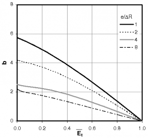
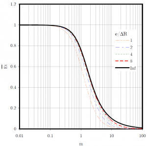
An additional deformation \beta_e is due to the mechanical loading generated by the sealed fluid pressure and the springs, O-rings, etc. Unfortunately, there exists no analytical solution of this problem and these angles must be calculated by FEA. However, these coefficients remain constant as long as the boundary conditions are unchanged. For example, the next figure presents the evolution of b=N/\lambda as a function of \bar{E_t} for a rectangular ring of length e, width \Delta r and radii ratio of 0.88. Here \lambda is the thermal expansion coefficient of the material.

The total coning angle \beta can be expressed in this way:


\beta=N \Delta T+\beta_e

Reference

Doust, T. & Parmar, A. An Experimental and Theoretical Study of pressure and thermal Distortions in a Mechanical Seal ASLE Transactions, 1986, 29, 151-159


Analytical modelling of mechanical face seals: post #1

Heat transfer in mechanical seals

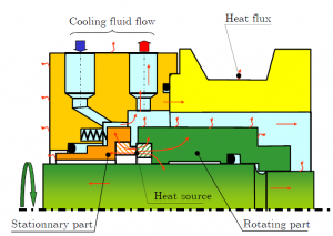
The first step of the model concerns heat transfer in the mechanical seal rings. As illustrated in the following figure, the mechanism of heat transfer in the vicinity of mechanical seal could be quite complicated.

However it has been shown that the heat generated in the seal interface is mainly transferred by conduction through the rings to the surrounding sealed fluid and then removed by convection. The heat transfer or convection coefficient is h_c. This parameter in mechanical seal can be evaluated using the Becker’s correlation (Becker 1963).


The previous figure shows the temperature distribution in the stationary part (part 1) of the seal when submitted to a heat flux q_1. The average resulting temperature rise of the face is \Delta T_1. Let us introduce the thermal efficiency E_{t1} of the ring 1 defined as the ratio of the thermal power P_1 entering the face to the average temperature rise.

E_{t1} = \frac{P_1}{\Delta T_1}= \pi \left( r_o^2-r_i^2\right)\frac{q_1}{\Delta T_1}

where r_o and r_i are respectively the outer and inner radii of the seal interface.

For a given seal design, this coefficient is only dependent on the thermal boundary conditions and can easily be calculated with a FEA software. If the seal width \Delta r=r_o- r_i is very small compared to the ring length e, an analytical expression of E_{t} can be found using the fin theory (Buck, 1989):


E_t = 2 \pi r_oe h_c \frac{\tanh m}{m}

where m is a heat transfer parameter including h_c and the thermal conductivity of the ring k :

m = \frac{e}{\Delta r} \sqrt{ \frac{h_c \Delta r }{k} }

A dimensionless version of the thermal efficiency can be expressed in this way:

\bar{E_t}=\frac{E_t}{2 \pi r_oeh_c }

The evolution of the dimensionless thermal efficiency is presented on the next figure as a function of the thermal parameter m (black solid curve). On the same figure, results obtained with FEA are presented when the seal ring length is varied from 1 to 8 and for a radii ratio of 0.88. It can be seen that the analytical solution is a reasonable approximation when the seal length is more than 4 times the seal width.

If the two seal rings are supposed to be at the same temperature \Delta T= \Delta T_1= \Delta T_2, a global thermal efficiency E_t, being the sum of the two individual thermal efficiencies, can be defined. The total thermal power P entering the seal faces is thus:

P=E_t \Delta T= \left(E_{t1}+ E_{t2}\right)\Delta T

References

Becker, K. “Measurement of Convective Heat Transfer from a Horizontal Cylinder Rotating in a Tank of Water,” International Journal of Heat and mass Transfer (6), 1963, pp. 1053-1062.

Buck, G. “Heat Transfer in Mechanical Seals”‘Proceedings of the 6th International Pump Users Symposium’, Houston, Texas, USA, 1989, pp. 9-15.

Analytical modelling of mechanical face seals: post #0

I will present in the next following posts a simple analytical model of mechanical seals. This model includes lubrication, asperity contact, heat transfer and seal faces deformations. It allows to calculate the fluid and contact pressure, the distance between the faces, the average temperature, etc. At the end of this serie, I will give an excel sheet containing the implemented analytical model. For more informations, it is possible to read the two following peer-review papers where the theoretical work is developped:

  1. Brunetière, N. “An Analytical Approach of the TEHD Behaviour of Mechanical Face Seals Operating in Mixed Lubrication,” IMechE, Part J, Journal of Engineering Tribology (224:12), 2010, pp. 1221-1233. (article in free access now: http://pij.sagepub.com/content/224/12/1221.abstract)
  2. Brunetière, N. and Apostolescu, A. “A Simple Approach to the ThermoElastoHydroDynamic Behavior of Mechanical Face Seals,” Tribology Transactions (52:2), 2009, pp. 243-255. (http://www.tandfonline.com/doi/abs/10.1080/10402000802441587)

Constitution and phenomenolgy of mechanical seals

Mechanical seals are sealing components used in rotating machines such as pumps, compressors, agitators, etc. They are used to seal every types of fluid (liquid, gas, paste, etc) in all industrial domains from nuclear to food industry.

Constitution of a mechanical seal

As can be seen, on the first figure, a seal is basically composed of a rotating ring linked to the shaft and of a static ring linked to the housing, one of this link being flexible to allow a good alignment of the faces. The rings are pushed in close contact under the action of elastic elements and the pressurised fluid. A thin fluid film of about one micrometer can build-up and generally separates the seal rings avoiding wear and increasing reliability. This film must, on the other hand, remain sufficiently thin to prevent leakage. The thickness of the lubricating film depends on many interacting physical phenomena as illustrated on the second figure. The central point is lubrication which controls the fluid flow of the fluid, the pressure distribution and the asperity contact. Because of the flexible link, the floating ring can encounter vibrations. Moreover, the geometry of the faces and thus the fluid film thickness is greatly affected by elastic distortions due to the pressure loading and thermal distortions resulting from the heat dissipated by friction in the contact. In some situations, phase change can take place in the contact. Another key parameter which is not illustrated here is the wear of the surfaces.

Phenomenology of mechanical seals

Bonjour, Hello

Je suis chargé de recherche CNRS à l’Institut Pprime de Poitiers. Ce blog présente certains de mes travaux de recherche sur la tribologie et plus particulièrement sur la lubrification des garnitures mécanique.

I am a CNRS researcher at the Institut Pprime in Poitiers, France. This blog presents some of my research work on tribology and more particularly on the lubrication of mechanical face seals.