Heat transfer in mechanical seals
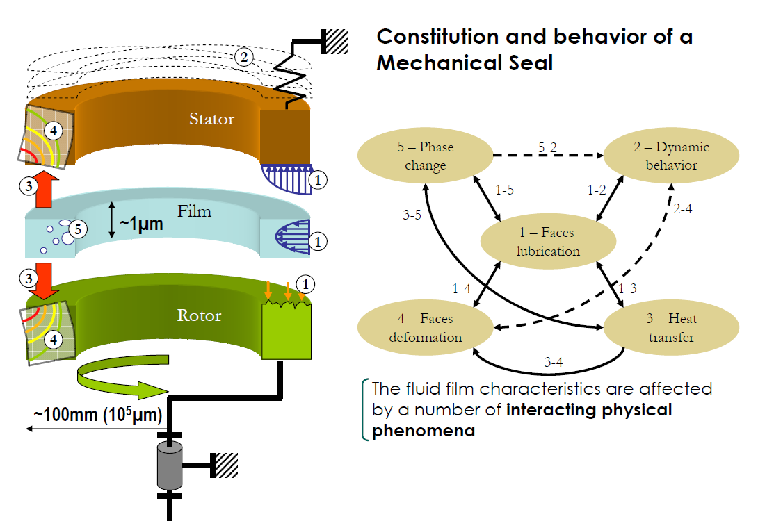
The first step of the model concerns heat transfer in the mechanical seal rings. As illustrated in the following figure, the mechanism of heat transfer in the vicinity of mechanical seal could be quite complicated.
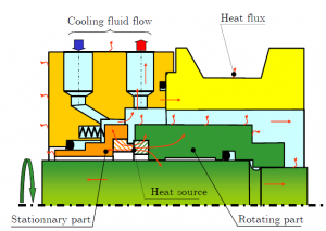
However it has been shown that the heat generated in the seal interface is mainly transferred by conduction through the rings to the surrounding sealed fluid and then removed by convection. The heat transfer or convection coefficient is  . This parameter in mechanical seal can be evaluated using the Becker’s correlation (Becker 1963).
 The previous figure shows the temperature distribution in the stationary part (part 1) of the seal when submitted to a heat flux
  . The average resulting temperature rise of the face is
  . Let us introduce the thermal efficiency
  of the ring 1 defined as the ratio of the thermal power
  entering the face to the average temperature rise.
\frac{q_1}{\Delta T_1}")
where  and
and  are respectively the outer and inner radii of the seal interface.
For a given seal design, this coefficient is only dependent on the thermal boundary conditions and can easily be calculated with a FEA software. If the seal width  is very small compared to the ring length
  , an analytical expression of
  can be found using the fin theory (Buck, 1989):

where  is a heat transfer parameter including and the thermal conductivity of the ring
  :
:

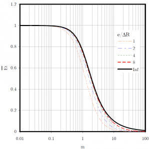
A dimensionless version of the thermal efficiency can be expressed in this way:

The evolution of the dimensionless thermal efficiency is presented on the next figure as a function of the thermal parameter (black solid curve). On the same figure, results obtained with FEA are presented when the seal ring length is varied from 1 to 8 and for a radii ratio of 0.88. It can be seen that the analytical solution is a reasonable approximation when the seal length is more than 4 times the seal width.
If the two seal rings are supposed to be at the same temperature  , a global thermal efficiency
  , being the sum of the two individual thermal efficiencies, can be defined. The total thermal power
  entering the seal faces is thus:
\Delta T")
References
Becker, K. “Measurement of Convective Heat Transfer from a Horizontal Cylinder Rotating in a Tank of Water,” International Journal of Heat and mass Transfer (6), 1963, pp. 1053-1062.
Buck, G. “Heat Transfer in Mechanical Seals”‘Proceedings of the 6th International Pump Users Symposium’, Houston, Texas, USA, 1989, pp. 9-15.